5 minutes
BGP Route Leaking - VRF to Global
The Problem
Recently I came across the requirement to leak routes from a VRF to the Global Route Table (GRT) and vice versa. The task took me longer than I care to admit, and my biggest stumbling block was deciding how exactly to go about it. The way described below is just one way to accomplish the task and specifically works for exchanges across dynamic routing protocols. Below is only one way to do it and the way that I found to be the most intuitive.
The Topology
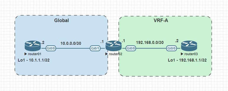
We are going to work off of an elementary topology with three routers. The first and third routers will exist within a single VRF, while the second router will have an interface in each VRF. The second router will peer with the first and third via BGP and leak routes from VRF-A to its GRT and vice versa.
router01 base config
hostname router01
!
interface Loopback1
 ip address 10.1.1.1 255.255.255.255
!
interface GigabitEthernet0/0
 ip address 10.0.0.2 255.255.255.252
 duplex auto
 speed auto
 media-type rj45
!
router bgp 65002
 bgp log-neighbor-changes
 neighbor 10.0.0.1 remote-as 6500
 !
 address-family ipv4
  redistribute connected
  neighbor 10.0.0.1 activate
 exit-address-family
!
Nothing special here; we just apply the IP addresses to the interfaces. Establish a BGP relationship with router02 and advertise our connected interfaces.
router02 base config
hostname router02
!
ip vrf VRF-A
 rd 1:1
 import ipv4 unicast map GLOBAL_TO_VRF
 export ipv4 unicast map VRF_TO_GLOBAL
 route-target export 1:1
 route-target import 1:1
!
interface GigabitEthernet0/0
 ip vrf forwarding VRF-A
 ip address 192.168.0.1 255.255.255.252
 duplex auto
 speed auto
 media-type rj45
!
interface GigabitEthernet0/1
 ip address 10.0.0.1 255.255.255.252
 duplex auto
 speed auto
 media-type rj45
!
!
router bgp 6500
 bgp log-neighbor-changes
 neighbor 10.0.0.2 remote-as 65002
 !
 address-family ipv4
  neighbor 10.0.0.2 activate
 exit-address-family
 !
 address-family ipv4 vrf VRF-A
  neighbor 192.168.0.2 remote-as 65001
  neighbor 192.168.0.2 activate
 exit-address-family
!
!
A couple noteworthy things in the router02 configuration. We create the VRF with the command:
ip vrf VRF-A
We then set a route descriptor of 1:1 with the following command:
rd 1:1
After creating our VRF, we place interface GigabitEthernet0/0 in that VRF with ip forwarding vrf VRF-A under the interface configuration.
interface GigabitEthernet0/0
  ip forwarding vrf VRF-A
router03 base config
hostname router03
!
interface Loopback1
 ip address 192.168.1.1 255.255.255.255
!
interface GigabitEthernet0/0
 ip address 192.168.0.2 255.255.255.252
 duplex auto
 speed auto
 media-type rj45
!
router bgp 65001
 bgp log-neighbor-changes
 neighbor 192.168.0.1 remote-as 6500
 !
 address-family ipv4
  redistribute connected
  neighbor 192.168.0.1 activate
 exit-address-family
!
Objective
The goal will be to just share 10.1.1.1/32 into VRF-A and 192.168.1.1/32 into the Global Route Table. When all is said and done, we should be able to ping from Loopback1 on router01 to Loopback1 on router03.
Configuration
Before we start importing and exporting routes, we will need to create a couple of route maps to identify the routes we want to import/export.
ip prefix-list GLOBAL_TO_VRF seq 10 permit 10.1.1.1/32
!
ip prefix-list VRF_TO_GLOBAL seq 10 permit 192.168.1.1/32
!
route-map VRF_TO_GLOBAL permit 10
 match ip address prefix-list VRF_TO_GLOBAL
!
route-map GLOBAL_TO_VRF permit 10
 match ip address prefix-list GLOBAL_TO_VRF
!
We know we want to grab the two /32 routes, so we create two prefix lists and then use those to identify the addresses within the route maps.
Once the route maps are built, they are applied to import/export statements within the vrf configuration.
ip vrf VRF-A
 import ipv4 unicast map GLOBAL_TO_VRF
 export ipv4 unicast map VRF_TO_GLOBAL
We are almost there. The last configuration required is to configure the route target on exported routes. This will tag any routes exported from VRF-A with the RD 1:1
ip vrf VRF-A
 route-target export 1:1
Validation
First, let’s check the Global Route Table on router02
router02#show ip route

Gateway of last resort is not set

      10.0.0.0/8 is variably subnetted, 4 subnets, 2 masks
C        10.0.0.0/30 is directly connected, GigabitEthernet0/1
L        10.0.0.1/32 is directly connected, GigabitEthernet0/1
B        10.1.1.1/32 [20/0] via 10.0.0.2, 01:20:51
B        10.3.3.3/32 [20/0] via 10.0.0.2, 01:29:03
      192.168.1.0/32 is subnetted, 1 subnets
B        192.168.1.1 [20/0] via 192.168.0.2 (VRF-A), 01:27:56
At the bottom, we see the route for 192.168.1.1/32 exported from VRF-A.
When we look at the route table for VRF-A we see the route for 10.1.1.1/32.
router02#show ip route vrf VRF-A

Routing Table: VRF-A

Gateway of last resort is not set

      10.0.0.0/32 is subnetted, 1 subnets
B        10.1.1.1 [20/0] via 10.0.0.2, 01:26:28
      192.168.0.0/24 is variably subnetted, 2 subnets, 2 masks
C        192.168.0.0/30 is directly connected, GigabitEthernet0/0
L        192.168.0.1/32 is directly connected, GigabitEthernet0/0
      192.168.1.0/32 is subnetted, 1 subnets
B        192.168.1.1 [20/0] via 192.168.0.2, 01:30:09
The route for 10.1.1.1/32 isn’t tagged with a RD or the name of VRF since it didn’t come from a particular VRF but the Global Routing Table. Once we have the routes properly injected into each route table we should now see them in the route tables of router01 and router03.
router03#show ip route

Gateway of last resort is not set

      10.0.0.0/32 is subnetted, 1 subnets
B        10.1.1.1 [20/0] via 192.168.0.1, 01:41:19
      192.168.0.0/24 is variably subnetted, 2 subnets, 2 masks
C        192.168.0.0/30 is directly connected, GigabitEthernet0/0
L        192.168.0.2/32 is directly connected, GigabitEthernet0/0
      192.168.1.0/32 is subnetted, 1 subnets
C        192.168.1.1 is directly connected, Loopback1
router01#show ip route

Gateway of last resort is not set

      10.0.0.0/8 is variably subnetted, 4 subnets, 2 masks
C        10.0.0.0/30 is directly connected, GigabitEthernet0/0
L        10.0.0.2/32 is directly connected, GigabitEthernet0/0
C        10.1.1.1/32 is directly connected, Loopback1
C        10.3.3.3/32 is directly connected, Loopback2
      192.168.1.0/32 is subnetted, 1 subnets
B        192.168.1.1 [20/0] via 10.0.0.1, 01:45:33
And finally, we should now be able to ping the loopback on router03 while sourcing from the loopback on router01.
router01#ping 192.168.1.1 source 10.1.1.1
Type escape sequence to abort.
Sending 5, 100-byte ICMP Echos to 192.168.1.1, timeout is 2 seconds:
Packet sent with a source address of 10.1.1.1
!!!!!
Success rate is 100 percent (5/5), round-trip min/avg/max = 5/7/10 ms
Summary
Overall this is a pretty quick and straightforward way to import/export routes from a VRF to the Global route table. It should be noted that this will only work if you are utilizing some sort of dynamic routing protocol. If you would like to use static/connected routes, some different approaches need to be taken. I have included some links to resources below.
Resources
Pretty comprehensive blog on route leaking between VRF and GRT using several different methods.
https://ipwithease.com/route-leaking-between-vrf-and-global-routing-table/
Cisco configuration guide, the one that got it over the line for me.
https://www.cisco.com/c/en/us/td/docs/ios-xml/ios/iproute_bgp/configuration/15-mt/irg-15-mt-book/irg-prefix-export.html
1056 Words
2021-08-12 00:00